Sunday, October 16, 2011

Solar Roast Truck Power System

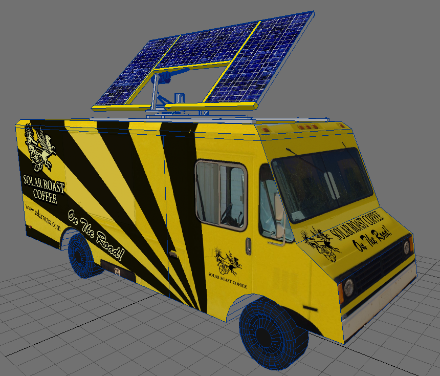
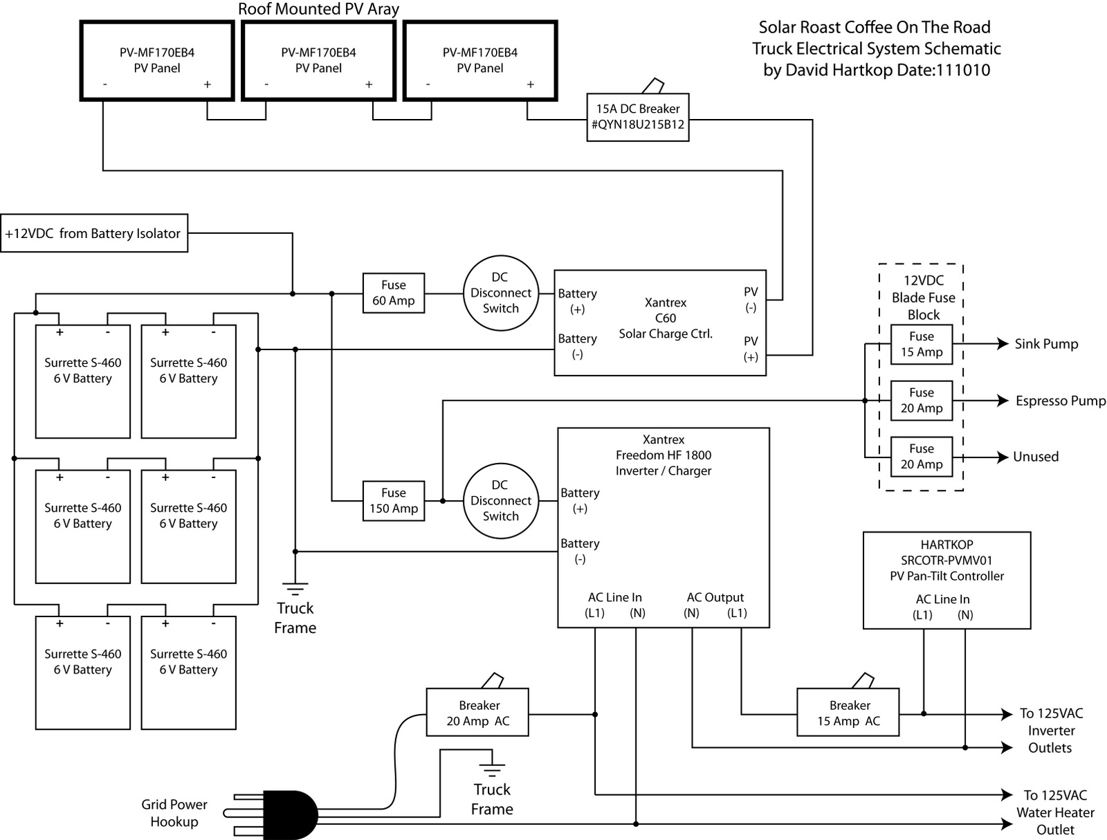
I built this system to use three panels and six batteries from our decomissioned Helios 4 Solar Roaster.  It also makes use of the Xantrex inverter charger that was already in the truck.  I added a Xantrex charge controller, and installed disconnects and appropriate fuses on everything.

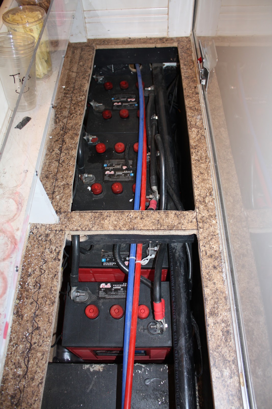
Six Rolls batteries drop into a compartment I opened up below the service counter.  I lined the floor with a poly liner and silicone caulk.  The compartment has a vent from the inside at one end.  I installed a 13 watt brushless AC fan at the other end to pull the hydrogen out.  I simply runs the whole time the inverter is on. 

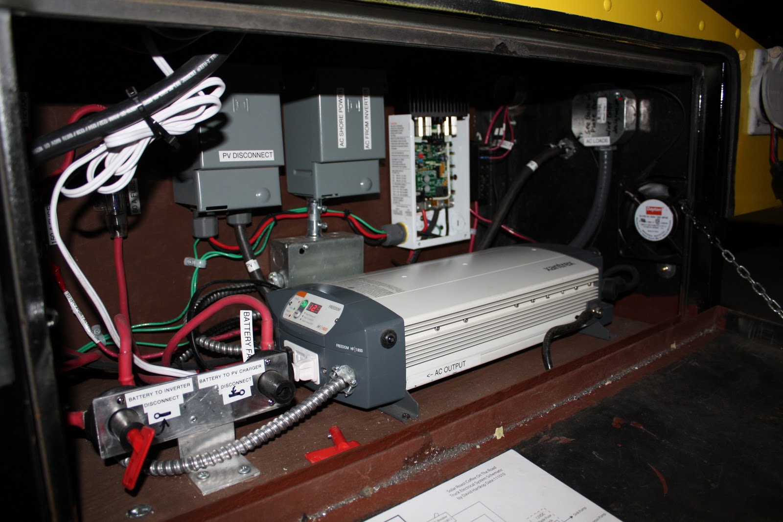
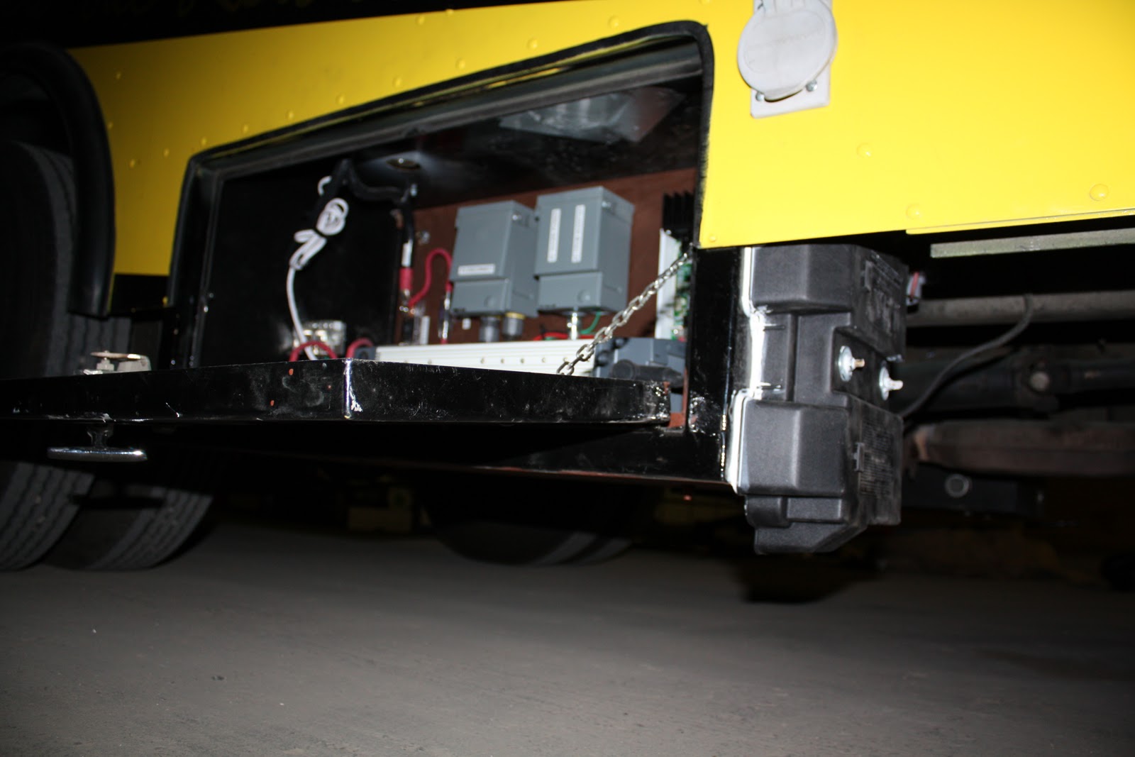
The power compartment below floor level.  It has a gasketed door.  I removed the old batteries, and cleaned it out with a wire brush before painting the inside with metal primer.  I built a base and back out of painted 1/2" plywood, and supported it on standoffs about an inch above the box floor.  I put a couple 1/4 inch holes in the bottom of the box to help with drainage, should water get in.  There is one exhaust vent in the back of the box behind the board that supports the disconnects.  I placed an intake fan at the front of the box.  It draws air in through a baffle, which directs air from the outside forward and then up.  This should prevent water splash from entering the compartment, while still allowing good airflow to cool all this stuff. 

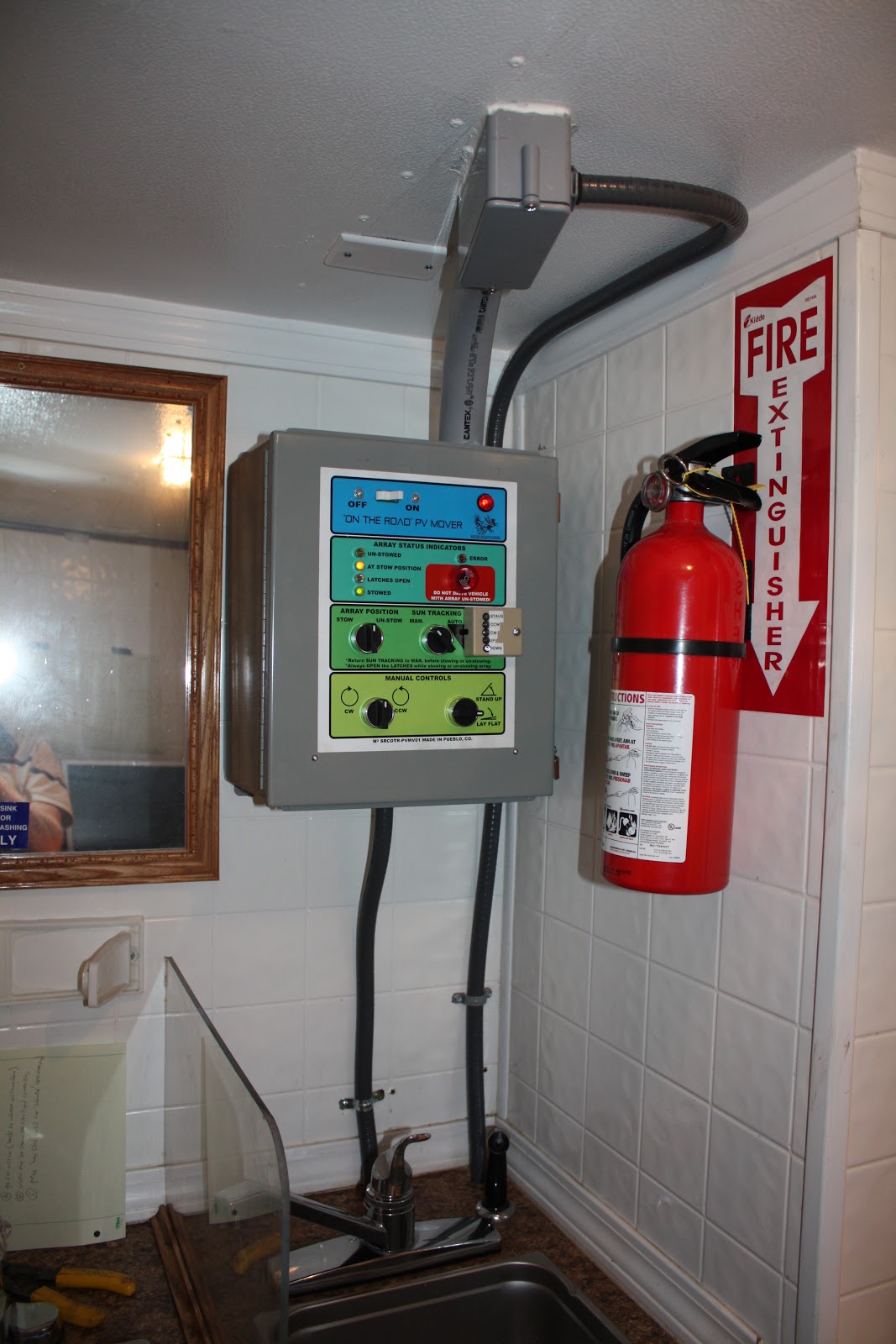
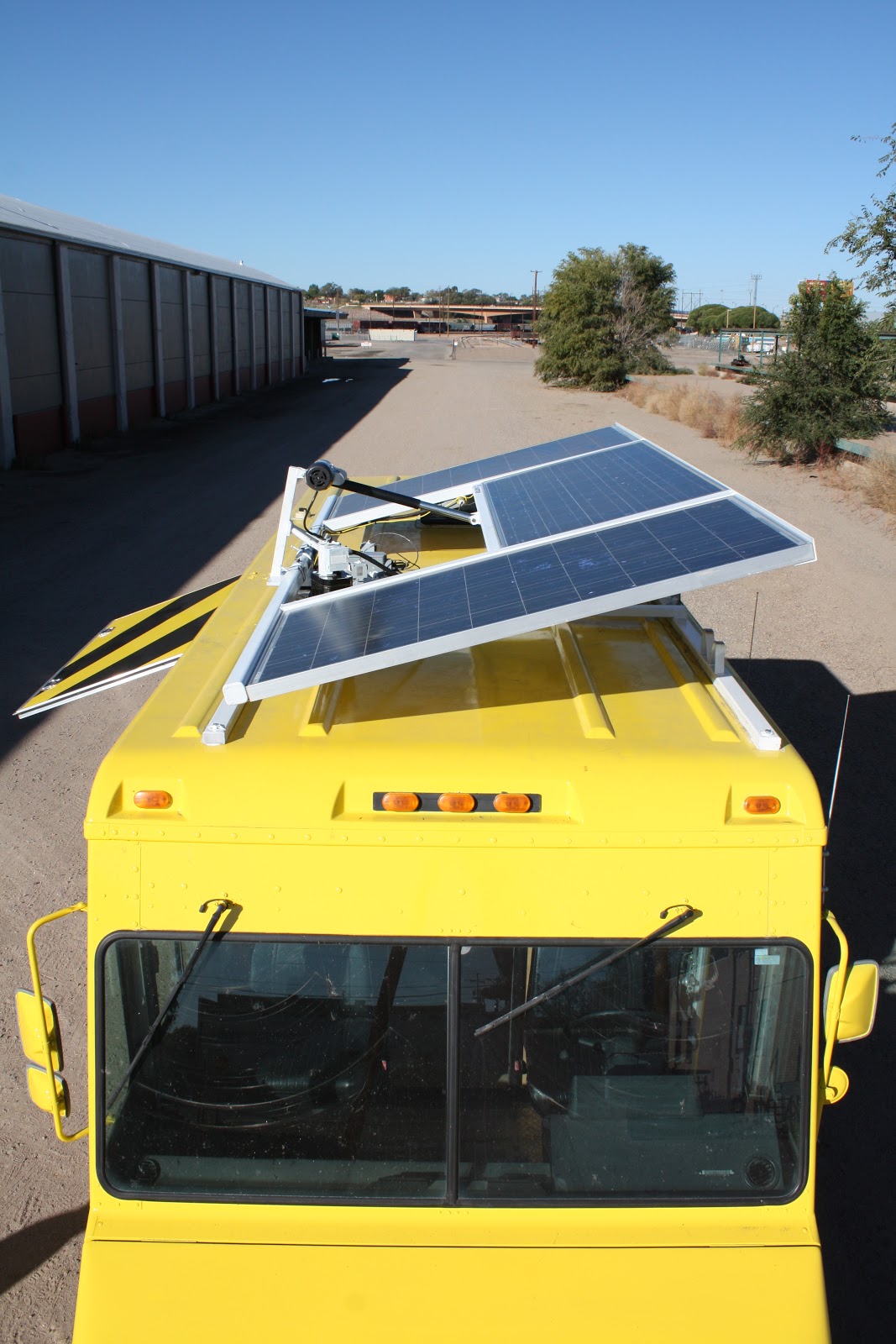
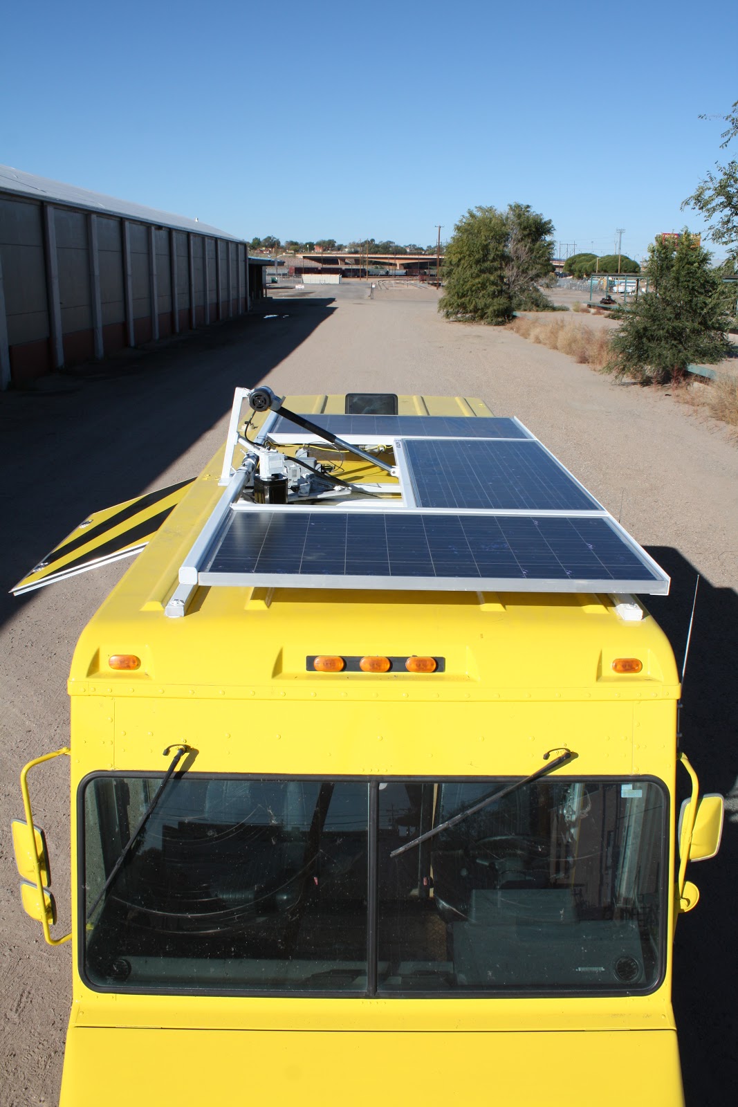
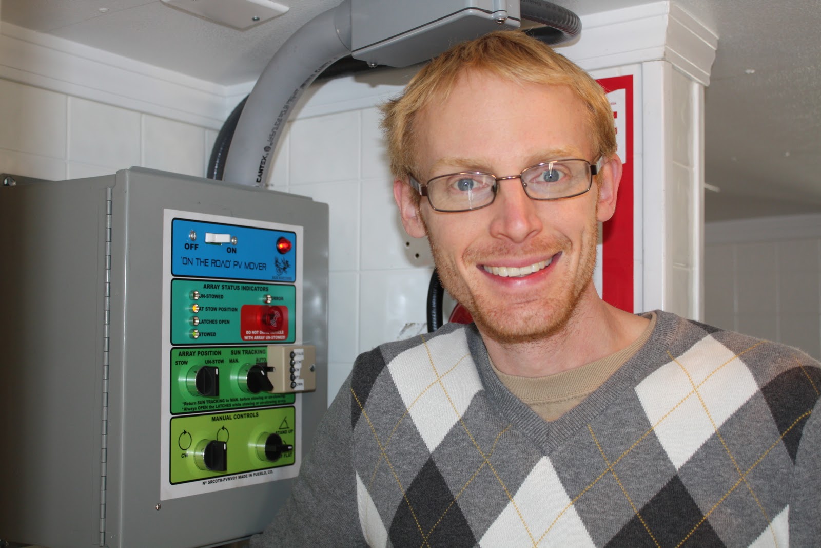
The PV pan-tilt control center (and fire-extinguisher).  The flex conduit from the top contains the feed from the PV, and the thick poly conduit from the top of the box contains the runs to the tracking motors and limit switches, sun position sensor, etc.

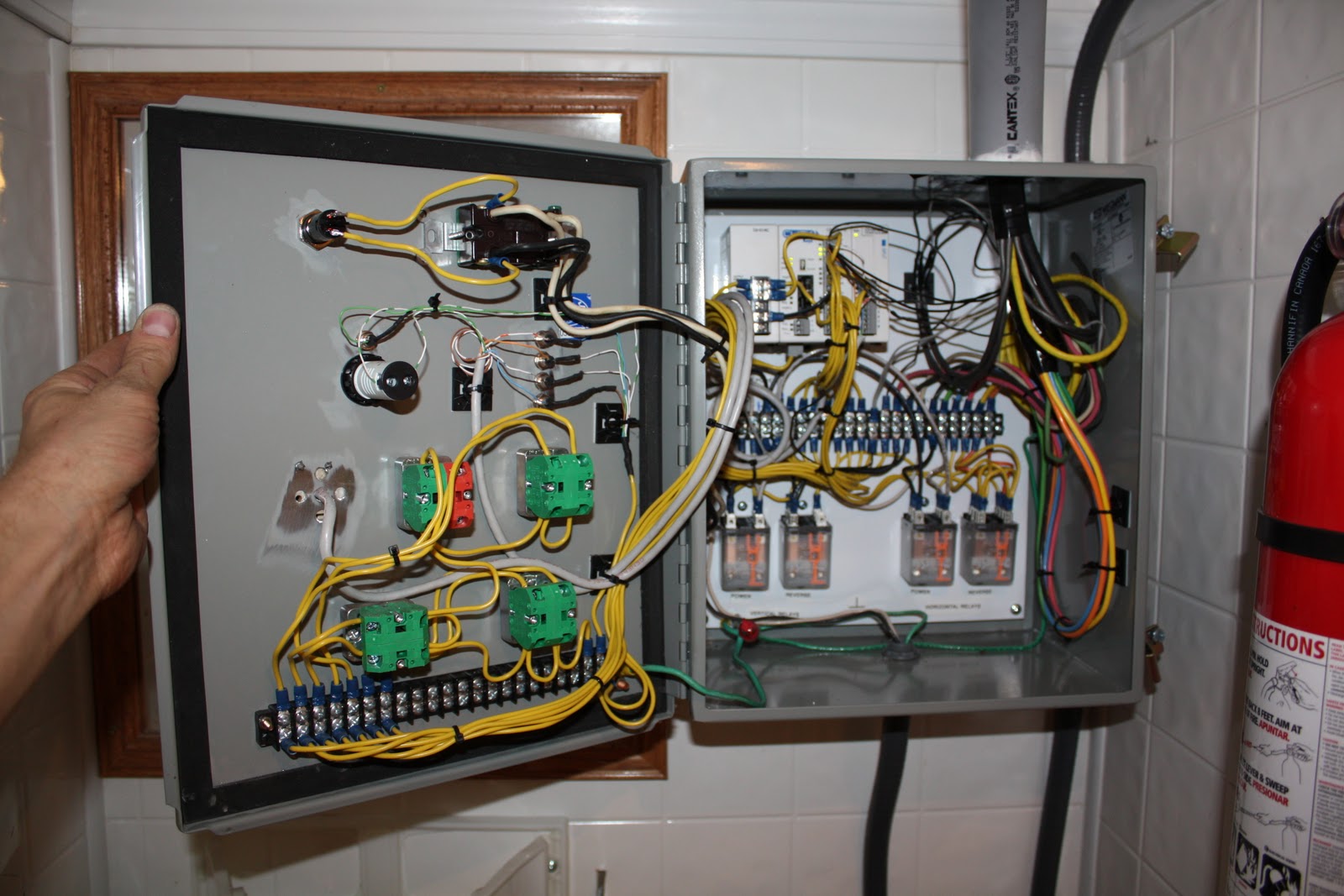
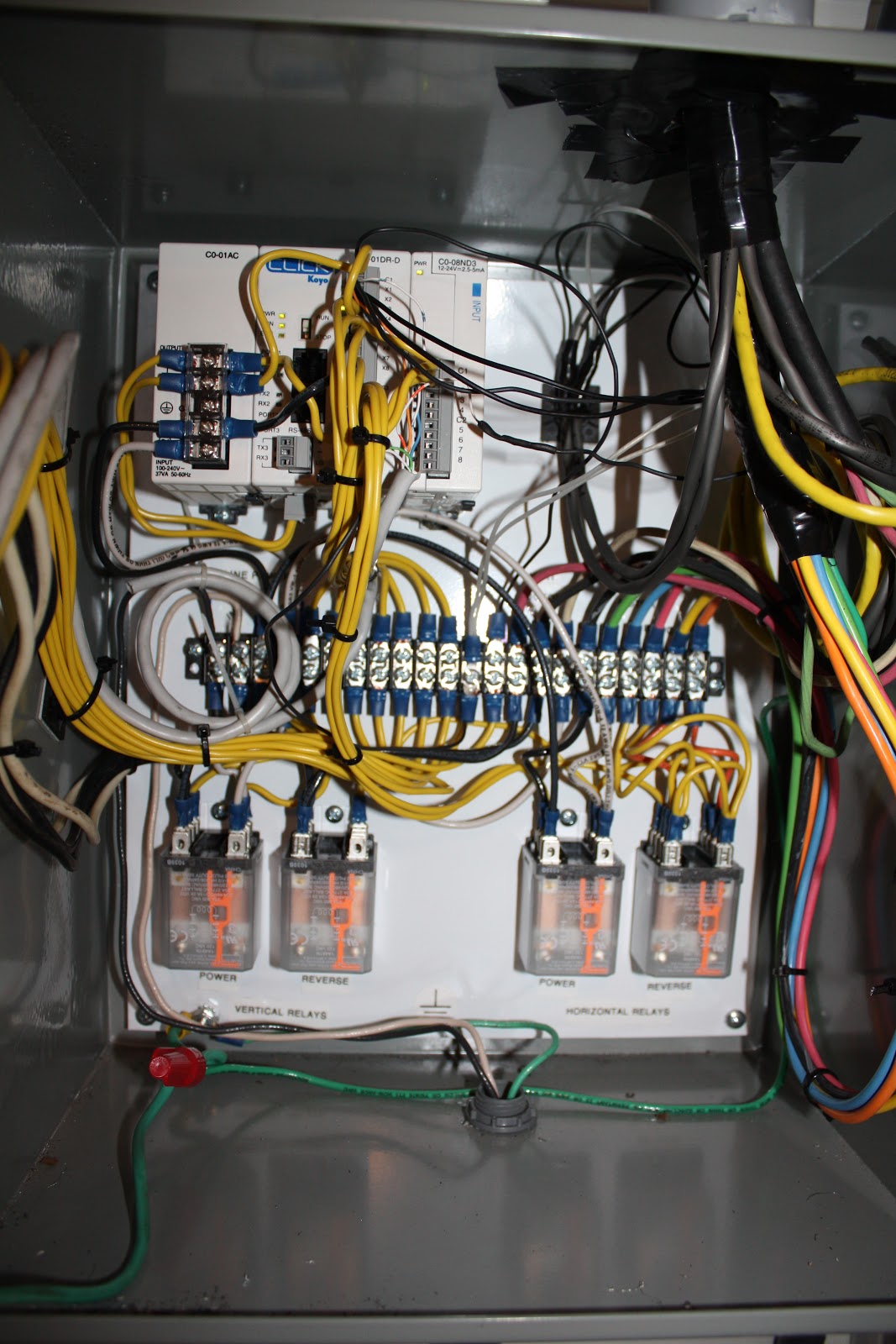
It started very neat and orderly, and became progressively less-tidy as the feeds from above entered the box!  The two reversible AC motors are controlled by the 4 relays at the bottom.  I built the control system around an AutomationDirect Koyo Click logic controller module, and programmed it with ladder logic.  The software is very basic right now, but will get an upgrade next month, with some better control limits and an automated panel-stow procedure.  I will be adding the solar tracking module shortly after that, once it has all been tested. 

The battery vent.

Design and Construction of the Pan-Tilt Solar Truck Mount

I settled on a pan-tilt mount that elevates three 170 watt solar modules to 50˚ with a linear motor, and rotates the whole system 360+˚  horizontally with a gearmotor driving a chain to a large sprocket.  I played with several other designs that involved balanced panels on elevating masts-mounts, or big hinged floppy panels, but everything was acting like a weather vane.  I did all my concept sketching an initial designs in Lighwave3D so I could animate and check for collisions and then measure the angles and lengths etc.
I had my friend Tyler double check my design in Solid Works, making sure main stress points will withstand 90 MPH wind loading.  Yes, it is all fine! 

This is the main plate, having the linear motor pivot at the top of the arm, a big hinge for elevating the panel, and a big round hole for the Igus slewing bearing. The bearing is really neat because it is literally just one big ring with polymer slides instead of moving parts.  It handles huge radial, axial, and moment loads, and is made to handle dust and dirt etc.  Plus it's aluminum, so it won't rust, so pretty cool :-)
The Roof Foundation frame distributes the 350 lb of hardware over an otherwise flimsy fiberglass/aluminum roof of the P-30 box truck.  I used six half-inch anchor bolts with big fender washers and LOTS of construction adhesive and silicone.  It is more glued down than bolted down, and then sealed to prevent water intrusion.  The red box is a vent van that must be avoided!
The main gear (which is stationary on the base plate) needed to be 20 inches in diameter to have suitable leverage against potential wind forces for the given motors I could afford to use.  I had Johnny's Boiler Shop in Pueblo use a water cutter to slice it out of 1/4" mild steel from a DXF file. 
I cut the rectangular steel tubes in my basement and then took them to the warehouse to weld, prime & paint.

I drilled 32 holes in the gear once I extended my drill-press's arm to have a big enough radius to reach in there!
The assembled horizontal pan mechanism.  The gear motor (at bottom) pulls the chassis around the stationary big gear.  The bearing has a 4 inch hole in the middle, through which all the power and control feeds will pass.  A trampoline spring tensions the chain by pulling a lever inward.  I eventually added a rigid turnbuckle to limit the spring's range (which seemed to solve the problem of launching the chain off the gear if you tried to stop the motor from moving clockwise!)
The panel frame welded into the hinge mechanism, the linear motor fittings attached.  I sprayed two coats of primer, two coats of enamel paint.  It took two days.  It was boring to do.  I wore a mask and listened to angsty dub-step on pandora. 


Jason drives a forklift like a mofo.

I managed not to scratch the truck OR the frame, thanks to tarps and cardboard:-)

It was difficult to attach the main gear to the foundation frame because it was already permanently attached to the panel frame via the hinge.  I debated making the hinge detachable, but that would make it harder to align (on the roof of the truck.) I also debated just welding it together on top of the truck, but then I'd either burn off the paint, or I'd have to do all the painting and priming up there.  Add to that the welding, and I'm sure I would have messed up the truck.  As it was, I just tore some pants on the sharp gear teeth.  SonOfA...

After this picture, it was more or less about bolting it together, putting on the motors panels, and then feeding a bundle of cables down through a waterproof turn-box I made in the center.  I used a pair of AC motors from Grainger, a linear motor rated at 1000 lb, and a neat little 1/16hp gearmotor that turns at 1/2rpm.  I did it with AC motors because I don't have to switch or control the high amperage of DC, I don't have to use electronic speed controllers, and because the rotation speed is related to the sine wave from the inverter.  This speed consistency is key because it lets me position the array with decent precision simply based on switch timing in the PLC.  (It consistantly takes 9 min 54 seconds to rotate the whole thing around once, and 2 minutes 10 seconds to fully elevate the array.  I also know that, if I elevate the array first for exactly 15 seconds, it will never crack the skylight off of the roof when it all rotates!)

Chris and Nathan of Solar Roast:On The Road.  They are happy to have their truck back!  I probably could have kept it for another week to tweak the software and touch the paint & tidy up the wire runs.  As it is, it works and they can now get out there and sell some coffee!


Full truck height with the little arm sticking up is 11.0 feet.  That's safe for most situations, and perfectly within the legal limitations of height for vehicles of this class (13 ft. in Colorado.)
The "On The Road" control panel.  I drew it in Illustrator and had it laser printed on a vinyl sticker. Interesting that to turn the array clockwise, one must turn the know counter-clockwise... hmm... why did I JUST notice this?!
Detail shot of my once-tidy now-functional Automation Direct PLC system. 

Yaay! 

Solar Roast Coffee: On the Road Truck!

This is how the Chevy P-30 box truck looked when Chris and Nathan bought it.  It is essentially a big aluminum delivery van, the kind used by FedEx.
The Proposed Design: 
The Finished Paint & Stickers:
I used photoshop and illustrator to make a thorough mockup of how the truck should be painted.  Nathan Stern's uncle has a business wrapping vehicles, so I then turned this image and the vector art over to him.

I was really impressed by the results!  The black detailing was painted, and the logo art is all cut and applied vinyl.